
Kestrel Build Guide

Materials
| Part | Quantity |
| Filament | 391g |
| FTW Micro Flywheels | 1 pair |
| FTW Merlins | 1 pair |
| FTW Hyperdrive Solenoid Double Sprung | 1 pc |
| FTW KiT | 1 pc |
| Narfduino | 1 pc |
| Out of Darts MOSFET Kit | 1 pc |
| Button Microswitch | 1 pc |
| XT-60 Male Connector | 1 pc |
| 18 AWG Silicone Coated Wire | Some |
| 22AWG Silicone Coated Wire | Some |
| Heat shrink | Some |
| 3mm Dowel Pin, 45mm Long | 2 pc |
| 3mm Dowel Pin, 36mm Long | 7 pc |
| 3mm Dowel Pin, 30mm Long | 2 pc |
| 3mm Dowel Pin, 24mm Long | 1 pc |
| 3mm Dowel Pin, 20mm Long | 2 pc |
| M3 Heat-Set Insert | 3 pc |
| M2x4 Flat Head Screw | 4 pc |
| M3x14 Flat Head Screw | 2 pc |
| M3 Knurled-Head Thumb Screw | 1 pc |
| M4x5 Flat Head Screw | 4 pc |
| M4x10 Socket Head Screw | 2 pc |
| Long Compression Spring | 1 pc |
| Small Compression Spring | 1 pc |
| TRUGLO .100" Fibers | 1 pc |
| HOLDster Magnets | 1 pair |
Printing
All STL files come with the models in their proper print orientations and will print without supports. Recommended settings are 200micron or smaller layer heights and 1.5mm shell thickness.
Assembly
Install threaded inserts into the top and grip using a soldering iron.

Using two 3x36mm pins, install either the fiber optic sights or picatinny rail


Install trigger using a 3x30mm pin and large spring.


Install the magazine release lever with a 3x30mm pin and small spring, or install the two-part magazine release using a 3x30mm pin, 3x36mm pin, and small spring.


Install the battery door using the M3 thumb screw


Insert motors into the frame using four M2x4 screws. Use the documentation for the KiT motor board to confirm orientation.

Thread the pusher onto the Hyperdrive solenoid, replacing the existing pusher.

Upload the Kestrel.ino firmware onto the Narfduino using these guides.
- Installing the Narfduino Driver - Blasters by Airzone
- Uploading Firmware with Arduino - Blasters by Airzone
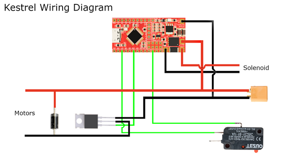
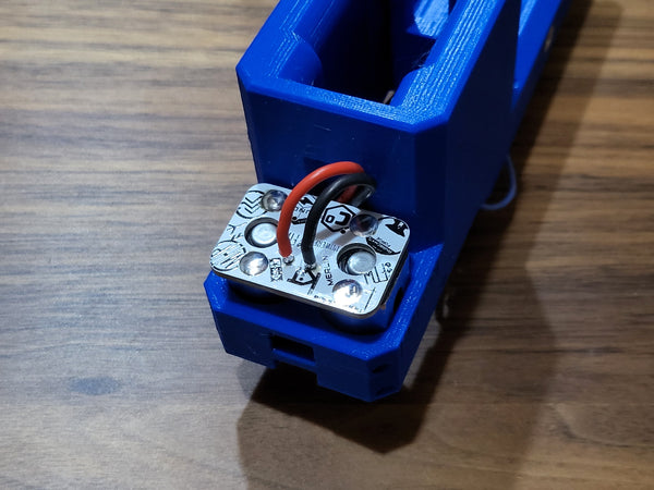
Wire up the electronics using the diagram below and reference pictures:


Install the microswitch using two 3x20mm pins

Install the solenoid using four M4x6 flat head screws. Tuck the microswitch wires and lipo wires in the center channel to keep them from being pinched. Tuck the Narfduino into the slot, thread the motor wires into their channel, and arrange the remaining wires to clear the magazine and pusher.

Connect the motors to the rest of the circuit using the KiT
Using four 3x36mm pins and one 3x45mm pin, assemble the lower half of the blaster


Using one 3x45mm pin and one 3x24mm pin, secure the top, ensuring that no wires are pinched and that they clear the magazine well.

Assembled Blaster
